
The ESP32 is a powerful microcontroller that supports various display modules, making it a great choice for projects requiring graphical output. In this tutorial, we’ll walk you through connecting and programming an ST7735 TFT display with an ESP32. From setting up your hardware to running a simple test program, you’ll learn everything you need to get started. Whether you’re a beginner or an experienced developer, this guide will help you bring visuals to your ESP32 projects effortlessly.
For this project, you will need an Esp32, a 128×160 display, some cables, and a USB-C cable.
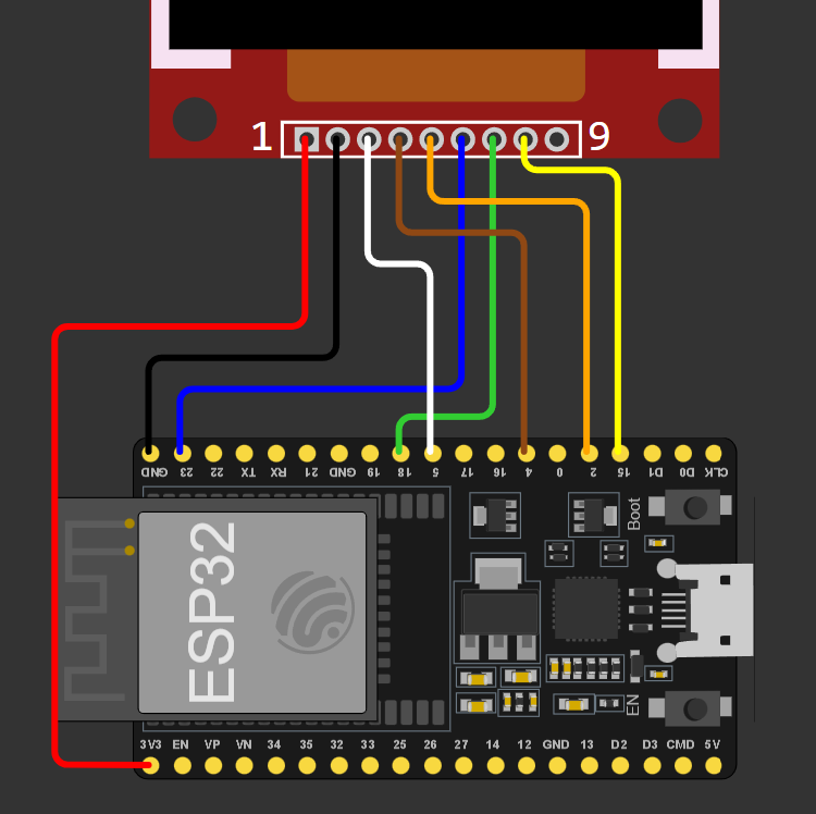
To connect the display to the Esp32, connect VCC to 3.3V, GND to ground, CS to pin 5,RST to pin 4, DC to pin 2, MOSI to pin 23 (Can also be called SDA in some Chinese displays), SCK to pin 18 and finally LED, BK or BL to any free pin or directly to 3.3V.
Before starting, make sure you have the PlatformIO IDE extension installed on VS Code. Then make a folder for your project and, in it, create a file named ‘platformio.ini’:
mkdir esp32-st7735
cd esp32-st7735
nano platformio.ini
In that file, paste the following configuration and then open VS Code:
[env:nodemcu-32s]
platform = espressif32
board = nodemcu-32s
framework = arduino
lib_deps = adafruit/Adafruit ST7735 and ST7789 Library@^1.11.0
code .This configuration should automatically install all Esp and Arduino libraries as well as the one we will use for our display.
We will now test our code by running some graphics on the display. Start by including the headers for Arduino, the display and SPI:
#include <Arduino.h>
#include <Adafruit_GFX.h>
#include <Adafruit_ST7735.h>
#include <SPI.h>
Then we will need to declare the pins the display will use, if you followed the instructions above, you can copy these values:
#define TFT_CS 5
#define TFT_RST 4
#define TFT_DC 2
After that, create your display using the pins define above:
Adafruit_ST7735 disp = Adafruit_ST7735(TFT_CS, TFT_DC, TFT_RST);Now we will create a scale function that will helps us convert 24bit RGB values to 16bit, we do that by scaling the components from 8bit to 5 or 6 bits and, finally, combining the 3 new values in an ‘uint16_t’:
// Change a number from one scale to another
float scale(float a, float min_a, float max_a, float min_b, float max_b)
{
    return min_b + ((a - min_a) * (max_b - min_b)) / (max_a - min_a);
}
// Convert a 24bit (8-8-8) RGB value to 16bit (5-6-5)
uint16_t fromRGB(uint8_t r, uint8_t g, uint8_t b)
{
    uint16_t rs = scale(r, 0, 0xFF, 0, 0b11111);
    uint16_t gs = scale(g, 0, 0xFF, 0, 0b111111);
    uint16_t bs = scale(b, 0, 0xFF, 0, 0b11111);

    return ((rs << 11) | (gs << 5) | bs);
}
On setup, begin Serial, initialize the display and fill it with black:
void setup()
{
    Serial.begin(115200); // Start Serial

    disp.initR(INITR_GREENTAB); // Initialize display

    disp.invertDisplay(false); // Set colors as 'normal'
    disp.fillScreen(ST7735_BLACK); // Paint the screen black
}
Finally, on loop, we start with RGB(0,0,0), which is black and fill the screen with all values until RGB(FF,FF,FF) which is white:
uint8_t cv = 0; // Color value
void loop()
{
    uint16_t color = fromRGB(cv, cv, cv++); // Make gray from cv
    Serial.printf("%u\n", (uint32_t)color); // Print color

    disp.fillScreen(color); // Fill screen with color

    vTaskDelay(10 / portTICK_PERIOD_MS); // Wait 100 ms
}
Now upload your code and this is what your display should look like:
Now that you know your display works, you can use functions like the ones below to draw all the graphics you might need:
disp.drawPixel(x0, y0, color);
disp.drawLine(x0, y0, x1, y1, color);
disp.drawRect(x0, y0, w, h, color);
disp.drawCircle(x0, y0, r, color);
disp.drawBitmap(x0, y0, bmp, w, h, color);
And that’s all, thanks for reading and stay tuned for more tech insights and tutorials. Until next time, and keep exploring the world of tech!